Reduce Remote CCTV Installation Costs in NZ
Compare grid, solar, wireless and hybrid CCTV designs using a practical lifecycle cost worksheet that exposes installation and maintenance costs.
By Maxsol Team

The most reliable way to reduce remote CCTV installation costs is to avoid unnecessary civil works, grid extensions and repeat site visits—not simply to choose cheaper cameras. Establish one performance scope, then compare grid-fed PoE, off-grid solar and hybrid designs over the project’s full lifecycle.
Solar and wireless links can lower costs at suitable sites, but neither is an automatic substitute for mains power or cable. PoE distributes power and data to compatible devices; it is not the original energy source. The lowest-cost design is the least expensive option that still meets the required coverage, uptime, throughput, environmental and maintenance conditions.
Establish a like-for-like scope and cost baseline
A credible comparison begins with identical requirements for every design option. Otherwise, a basic solar proposal may appear cheaper than a grid-fed system simply because it includes less storage, lower recording quality or a weaker backhaul specification.
Document these requirements before requesting equipment or installation estimates:
- Number, type and position of cameras
- Camera power consumption, including night-time functions
- Required resolution, frame rate and compression settings
- Local or central recording requirements
- Retention period and expected traffic per camera
- Live-view and remote-access requirements
- Maximum acceptable outage or loss of recording
- Distances between cameras, network nodes and the monitoring point
- Existing poles, ducts, cabinets, fibre, copper and power circuits
- Terrain, vegetation, access restrictions and exposure
- Available sunlight at the actual panel position
- Wireless line of sight and likely radio interference
- Maintenance access, travel time and site-entry requirements
- Expected project life and replacement assumptions
Build the cost baseline by work package
Use a worksheet that separates one-off installation costs from recurring and replacement costs.
| Cost category | Items to include | Common omission |
|---|---|---|
| Site investigation | Desktop design, site visit, route survey, line-of-sight check, solar shading assessment | Treating a desktop map as a complete survey |
| Civil works | Trenching, directional drilling, reinstatement, traffic or access management | Surface restoration and difficult ground |
| Grid connection | Cable route, switchboard work, metering, electrical design and connection work | Distance from the nearest usable supply |
| Structures | New poles, brackets, foundations and cabinet mounts | Engineering or access equipment |
| Power hardware | Power supplies, solar modules, batteries, controllers, protection and conversion equipment | DC conversion losses and standby loads |
| Network transport | Copper, fibre, wireless radios, switches, optics and surge protection | Termination, configuration and test labour |
| CCTV equipment | Cameras, recording, storage, licences and mounting hardware | Storage growth and replacement drives |
| Labour | Installation, termination, alignment, programming and documentation | Travel, inductions and restricted access hours |
| Commissioning | Image checks, recording tests, network tests and customer handover | Return visits caused by incomplete configuration |
| Operating costs | Electricity, data plans, software subscriptions and site charges | Price changes over the project life |
| Maintenance | Cleaning, vegetation control, inspections, fault finding and travel | Remote-site call-out costs |
| Replacements | Batteries, damaged cables, power supplies, radios and other finite-life components | Labour and access equipment for replacement |
For each option, calculate:
Lifecycle cost = initial design and installation + operating costs + planned maintenance + expected replacements + risk allowance − residual value
Use the same project period and assumptions for every option. Keep uncertain items visible rather than hiding them inside a single contingency figure.
Compare grid extension and solar power
Grid power is usually attractive where a compliant, usable supply is already close to the camera location. It can become costly where a new circuit requires long trenching routes, road crossings, substantial reinstatement or work across property boundaries.
Off-grid solar can avoid part of that work, but it introduces a different engineering task: balancing the continuous electrical load against generation, energy storage, weather variation and maintenance access.
Like-for-like power architecture decision matrix
| Consideration | Grid-fed PoE | Off-grid solar with PoE distribution | Feasible hybrid approach |
|---|---|---|---|
| Primary energy source | Electricity grid | Solar generation and battery storage | Grid at one location; solar at selected remote nodes |
| PoE role | Distributes power from a mains-powered PoE source | Distributes power after suitable solar, battery and conversion stages | Used independently at grid and solar nodes |
| Best fit | Supply is nearby and civil work is manageable | Grid extension is impractical and the site has suitable solar exposure | A site has mixed access, power and distance conditions |
| Main installation cost | Electrical work, cable route and trenching | Panel, battery, controller, structure and power conversion | More design interfaces, but less civil work at selected nodes |
| Key design constraint | Connection route and electrical work | Energy budget, shading, temperature and autonomy target | Compatibility and monitoring across different power architectures |
| Ongoing cost | Electricity and electrical maintenance | Inspection, cleaning and eventual component replacement | Combination of grid and solar operating costs |
| Typical risk | Civil-work escalation or delayed connection | Under-sized generation or storage | Added system complexity |
| Expansion | Often straightforward within circuit and network limits | Extra load may require revised generation and storage | Expansion assessed node by node |
A hybrid design does not need to mean two power sources at every camera. One practical arrangement is a grid-powered recording and network hub connected wirelessly to solar-powered camera nodes. Another is to retain existing grid-fed cameras while using solar only for locations where extending power would trigger disproportionate civil work.
Size solar from the load, not the camera count
Begin with the actual or documented consumption of every continuously powered component:
- Camera
- Infrared or white-light illumination
- Wireless radio
- PoE injector or switch
- DC converter
- Heater, fan or cabinet equipment
- Monitoring and control hardware
Then account for conversion losses, temperature limits, local shading, seasonal conditions and the required reserve. Do not size a system by comparing nominal battery watt-hours with camera wattage alone.
For example, under a hypothetical design assumption, a 10W camera, a 6.5W radio and 4W of supporting power hardware create a 20.5W load before allowing for conversion losses or design margin. Running continuously, that represents 492Wh per day. This is an arithmetic illustration only—not a runtime prediction or a sizing recommendation.
The Maxsol CS12060 120W and 768Wh solar system documents a 120W monocrystalline panel, a 12.8V 60Ah 768Wh LiFePO4 battery, an MPPT controller and three DC12V outputs, with RS485 optional. Its nominal 768Wh battery rating is not the same as usable delivered energy.
Before specifying it, confirm the current controller limits for PV voltage, current and power, as well as battery charging temperatures, protection settings and the supplied configuration. A PoE camera may also require appropriate conversion and PoE sourcing hardware because the documented outputs are DC12V. No universal autonomy, service-life or round-the-clock runtime should be assumed.
Evaluate wireless backhaul against new cabling
Wireless backhaul can reduce remote CCTV installation costs where a cable route would require extensive trenching, poles or reinstatement. Its viability depends on line of sight, terrain, vegetation, interference, mounting stability and the throughput needed after protocol and environmental overheads.
Compare three transport options separately from the power source:
| Transport option | Potential advantage | Principal limitation | Check before selection |
|---|---|---|---|
| Reuse existing copper or fibre | Minimises new civil work | Existing cable may be damaged, undocumented or unsuitable | Test condition, topology, capacity and surge exposure |
| Install new copper or fibre | Predictable physical path when properly designed | Trenching and distance can dominate cost | Route, distance, ducts, termination and future capacity |
| Point-to-point wireless | Avoids continuous cable routes | Requires a viable radio path and suitable spectrum use | Line of sight, interference, mounting and local radio rules |
Wireless does not eliminate power requirements at the remote end. A camera and radio still need grid, solar or another suitable supply.
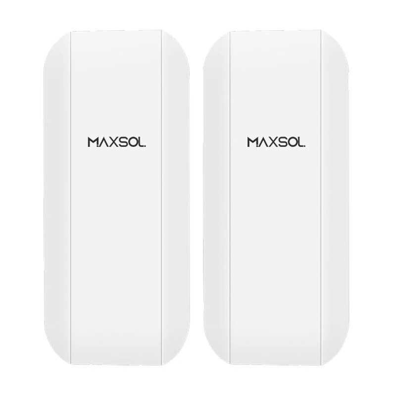
The Maxsol CPE295 5.8GHz directional wireless CPE documents 5.8GHz operation, a 2×2 14dBi directional MIMO antenna, one Gigabit LAN port, IEEE 802.3af/at or 9–48V DC power support, and 6.5W full-load consumption. Product range and wireless-rate labels do not guarantee site distance or application throughput. Verify line of sight, interference, link capacity and applicable New Zealand radio requirements for the planned configuration.
The CPE295 and CS12060 are selection examples, not a tested compatible bundle. Their voltages, power path, connectors, protection, environmental arrangement and total energy budget must be checked as a complete system.
Do not force wireless where cable is already viable
Wireless may add unnecessary alignment and interference risk when an existing serviceable cable is available. Conversely, installing new cable solely because it feels more familiar can be expensive where the route crosses hard surfaces, waterways, steep ground or heavily used areas.
For runs where copper remains practical, review the design choices in this guide to extending PoE for IP cameras over longer distances. Where fibre is preferred for distance, isolation or bandwidth, use the SFP uplink guide for CCTV fibre networks to assess optics, fibre type, link topology and switch interfaces. These transport decisions should remain separate from the choice between grid and solar energy.
Reduce repeat visits through surveys and bench checks
Remote-site labour can exceed the cost of a small component, particularly when each visit requires travel, access coordination or elevated work. A disciplined survey and pre-commissioning process reduces avoidable returns.
Complete a site survey before final equipment selection
Record:
- Camera fields of view and mounting heights
- Cable routes and measured distances
- Existing power points and circuit information
- Solar panel orientation, shading and mounting area
- Wireless path clearance and potential obstructions
- Cabinet space, ventilation and environmental exposure
- Earthing and surge-protection requirements
- Network hand-off and addressing requirements
- Safe maintenance access
- Photographs, marked plans and installation notes
For a wireless path, inspect more than the two endpoints. Vegetation or terrain near the middle of the path can affect clearance even when each mounting point appears to see the other.
For solar, assess the proposed panel location rather than relying on general regional conditions. Buildings, trees, hills, seasonal sun angles and future vegetation growth can materially change the energy available at a specific site.
Bench-check the assembled system
Before dispatching installers, assemble and test as much of the system as practical:
- Apply the intended power arrangement
- Confirm camera startup and night-mode load
- Check PoE negotiation where applicable
- Configure addresses, passwords and time settings
- Verify recording and remote access
- Load the expected radio configuration
- Confirm switch and port settings
- Label cables, injectors, converters and enclosures
- Save configuration backups
- Prepare a commissioning checklist
A short bench test does not prove long-term field performance, but it can expose mismatched voltages, missing adaptors, incorrect configurations and failed components before they create another site visit.
Common causes of avoidable rework include assuming all PoE implementations are interchangeable, overlooking startup or night-time load, using estimated rather than surveyed distances, and shipping unconfigured radios to site.
Include maintenance, replacements and operating costs
The lowest installation quote is not necessarily the lowest-cost remote CCTV system. Include costs that occur after commissioning, particularly when access is difficult.
Grid-fed system costs
Allow for:
- Electricity consumption
- Electrical inspections or repairs where required
- Damage to exposed power or network routes
- Network hardware and storage replacement
- Software, connectivity or monitoring subscriptions
- Travel and labour for faults
Solar-powered system costs
Allow for:
- Panel inspection and cleaning where site conditions require it
- Vegetation management and shading checks
- Battery condition monitoring and eventual replacement
- Controller, protection and conversion hardware faults
- Water ingress or enclosure deterioration
- Reassessment when cameras or radios are upgraded
- Travel and access equipment for maintenance
Do not assign a battery replacement interval without support from the current product documentation, operating temperature, discharge profile and charging conditions. Battery chemistry alone does not establish service life at a specific CCTV site.
Wireless system costs
Allow for:
- Antenna or radio realignment
- Mounting movement or damage
- Vegetation growth into the path
- Interference investigation
- Firmware and configuration management
- Replacement following surge or environmental damage
- Subscription costs if a separate data service is used
A wired link may have higher initial civil costs but lower routine attention. A wireless or solar node may be cheaper to install but more costly to reach when maintenance is needed. The worksheet should expose that trade-off.
Choose the lowest viable lifecycle cost
Eliminate technically unsuitable options before comparing cost. A cheap design that cannot meet the required uptime, image quality or recording performance is not a saving.
Use this sequence:
- Confirm the functional scope. Fix camera coverage, recording, retention, remote access and outage tolerance.
- Reuse suitable infrastructure. Test existing poles, ducts, cables, cabinets and power rather than assuming they can or cannot be reused.
- Compare power options. Price nearby grid supply, full grid extension, off-grid solar and mixed-site hybrid designs.
- Compare transport independently. Assess existing cabling, new copper, fibre and wireless backhaul.
- Calculate the complete load. Include every device and conversion stage, not just cameras.
- Add all enabling work. Include trenching, poles, foundations, protection, access equipment and commissioning.
- Model operating and replacement costs. Use a common project period and clearly documented assumptions.
- Apply a risk allowance. Separate uncertain civil, wireless, solar and access costs so decision-makers can see them.
- Select the least expensive compliant design. Do not choose solely on equipment purchase price.
A simple decision rule is:
- Prefer grid-fed PoE when usable power is nearby and the cable route is straightforward.
- Consider solar-powered nodes when grid extension is costly and the site supports a defensible energy design.
- Consider wireless backhaul when trenching is the main cost and the radio path is viable.
- Use a hybrid design where different parts of the site have materially different power or transport constraints.
The next step is to complete the lifecycle worksheet with surveyed site data, then compare the linked Maxsol models against the required port count, total load, distance, power architecture, environment and management needs. Confirm current datasheets and the supplied configuration before treating any product as compatible with the complete CCTV design.