12V vs 24V vs 48V for Outdoor PoE Networks
Compare 12V, 24V and 48V outdoor PoE DC power, including voltage drop, startup sag, converter limits, protection and commissioning checks.
By Maxsol Team

For outdoor PoE networks, 48V DC is usually the practical choice for longer cable runs or higher loads because it carries the same power at a lower current than 12V or 24V. Lower current means less voltage drop, lower cable loss and more design margin. A 24V system can be a useful middle ground, while 12V is generally better suited to short, low-power branches or equipment designed specifically for a 12V supply.
However, nominal voltage alone does not determine compatibility. A reliable design must account for the source’s complete voltage range, battery discharge and charging behaviour, startup sag, converter limits, cable resistance, branch protection and the actual input range of every connected device.
| Design consideration | 12V DC | 24V DC | 48V DC |
|---|---|---|---|
| Current for the same power | Highest | Moderate | Lowest |
| Cable-loss sensitivity | Highest | Moderate | Lowest |
| Practical distribution distance | Usually shortest | Medium | Usually longest |
| Common role | Small direct-DC loads and short branches | Solar systems, converters and intermediate distribution | PoE distribution and higher-power loads |
| Startup-sag tolerance | Often limited by high current | Better than 12V | Usually best when equipment supports the full range |
| Main compatibility risk | Source voltage may fall below load minimum | “24V PoE” may use a proprietary or passive arrangement | A nominal 48V source may exceed some DC inputs |
| Protection consideration | High branch current | Moderate branch current | Higher voltage rating required for switching and protection devices |
These are general comparisons, not universal limits. Select the voltage only after mapping the full system.
Map sources, loads and voltage ranges
Begin with an electrical block diagram rather than a list of nominal voltages. Record every source, conversion stage and load from the solar panel and battery through to the cameras, radios, switches and auxiliary equipment.
For each item, document:
- minimum and maximum operating input voltage;
- continuous and peak input current;
- startup or inrush current;
- output voltage range;
- continuous output-power limit;
- conversion efficiency across the expected load range;
- low-voltage cut-off and restart thresholds;
- polarity and connector or terminal arrangement;
- PoE voltage, pinout and detection or negotiation method;
- environmental and temperature restrictions.
A battery described as “12V” does not stay at exactly 12V. Its terminal voltage changes with chemistry, state of charge, charging mode, load and temperature. The same principle applies to nominal 24V and 48V battery banks. Controllers and converters must accept the real minimum and maximum voltage, not just the name printed on the system.
For example, the Maxsol CS12060 120W and 60Ah solar system documents a 120W monocrystalline panel, a 12.8V 60Ah 768Wh LiFePO4 battery, an MPPT controller and three DC12V outputs. RS485 is optional. Those figures identify the system’s nominal architecture, but they do not establish the usable energy delivered to a particular PoE load. Designers still need to confirm controller limits, battery charging temperatures, conversion losses, low-voltage cut-off behaviour and the load profile.
Battery chemistry affects voltage behaviour, charging and protection, but it is only one layer of the design. For a focused overview, see the guide to LiFePO4 battery benefits for solar CCTV.
Check each interface, not just each device
Treat every connection between components as a compatibility boundary. A converter may accept the battery voltage but fail to provide enough output power. A switch may have the required total PoE budget but not support the required voltage or power on the intended port.
PoE terminology also needs care. A stated voltage does not prove IEEE powered-device detection, classification or negotiation. Passive power, proprietary pinouts and standards-based PoE are not interchangeable. Confirm:
- input voltage range;
- output voltage under load;
- polarity;
- powered pairs or pinout;
- detection and negotiation behaviour;
- maximum continuous output per port;
- total shared power budget.
Per-port and total PoE loading should be calculated separately from the DC distribution loss. The PoE power-budget guide for security cameras explains how to account for camera demand, port limits and shared switch capacity.
Allow for startup sag and converter limits
A system that works after startup may still fail when a camera heater, infrared illuminator, radio or switch powers up. During startup, current can rise rapidly and pull the battery or branch voltage below the converter’s minimum input threshold.
This transient voltage reduction can come from several sources at once:
- internal battery resistance;
- battery-management system limits;
- controller current limits;
- cable and connector resistance;
- undersized conductors;
- converter inrush current;
- simultaneous load startup;
- cold equipment or battery conditions;
- a weak or partially charged battery.
A converter that shuts down may restart automatically, causing repeated boot cycles. This can look like a networking fault even though the root cause is on the DC side.
Use minimum input voltage as a hard design boundary
For each converter or switch, estimate the lowest voltage that can reach its terminals during the worst credible load event:
Minimum device voltage = minimum source voltage − cable drop − protection and connector drop − transient sag allowance
The result should remain above the device’s documented minimum input voltage with a reasonable engineering margin. Do not assume that a controller’s low-voltage cut-off will protect downstream equipment from unstable operation; the equipment may reset before the controller disconnects the battery.
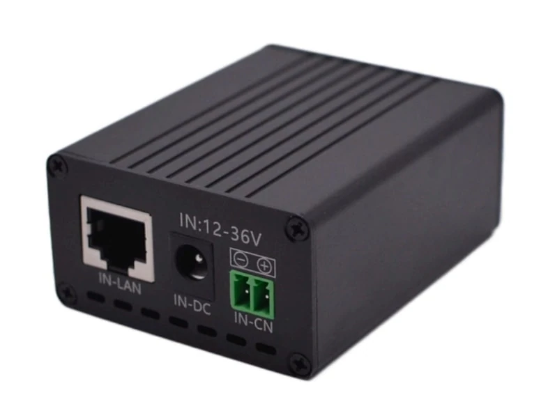
The Maxsol POE24V DC-to-PoE converter documents a 12–36V DC input, an adjustable 12–57V PoE output, Gigabit Ethernet and an LCD voltage display. Its documented continuous load when converting 12V to 48V is no more than 30W. A stated maximum conversion efficiency of up to 94% should not be treated as the guaranteed efficiency for every voltage, load or temperature.
IEEE powered-device detection or negotiation is not established by those specifications. Before connecting equipment, verify output voltage, polarity, pinout, protocol and power demand. In particular, do not use the adjustable output as a substitute for a compatibility check.
Avoid designing at the converter’s headline limit
Continuous conversion capacity may reduce with high enclosure temperature or unfavourable input and output conditions. Even when derating is not explicitly stated, a robust design avoids operating continuously at the absolute published maximum.
Include power for the converter itself when sizing the source. If a load requires 30W and the conversion stage is not 100% efficient, the battery must supply more than 30W. Use a conservative efficiency assumption appropriate to the chosen equipment rather than a best-case headline figure.
Calculate round-trip cable voltage drop
DC voltage drop must be calculated over the complete current path: the positive conductor to the load and the return conductor back to the source. Using only the one-way distance understates both resistance and loss.
The basic method is:
Round-trip resistance = conductor resistance per metre × one-way distance × 2
Voltage drop = current × round-trip resistance
Cable power loss = current² × round-trip resistance
For an approximate conductor calculation:
Resistance = resistivity × conductor length ÷ conductor cross-sectional area
Actual resistance varies with conductor material, construction and temperature. Manufacturer cable data is preferable to a generic resistivity value.
Hypothetical comparison
The following is an illustrative calculation only. It is not measured product performance.
Assume:
- load power: 120W;
- one-way DC cable distance: 30m;
- round-trip conductor length: 60m;
- copper conductor area: 4mm²;
- assumed copper resistivity: 0.0175Ω·mm²/m;
- constant nominal power for simple comparison;
- no connector, fuse, terminal or conversion losses;
- conductor temperature effects ignored.
Calculated round-trip resistance:
0.0175 × 60 ÷ 4 = 0.2625Ω
| Nominal distribution voltage | Approximate current at 120W | Calculated voltage drop | Calculated cable loss |
|---|---|---|---|
| 12V | 10A | 2.63V | 26.25W |
| 24V | 5A | 1.31V | 6.56W |
| 48V | 2.5A | 0.66V | 1.64W |
This example shows why raising the distribution voltage can materially reduce loss. Doubling voltage halves current for the same power; because resistive loss is proportional to current squared, the reduction in loss can be substantial.
Real constant-power loads complicate the calculation. As voltage at the load falls, the equipment may draw more current to maintain output power. That additional current causes more cable drop, which can create a reinforcing decline. A detailed design should therefore recalculate current at the estimated minimum terminal voltage rather than relying only on nominal values.
Also include resistance from:
- fuse holders and breakers;
- isolation switches;
- terminal blocks;
- plug-and-socket connectors;
- surge-protection devices;
- ageing or contaminated contacts;
- shared negative or return conductors.
Do not assume Ethernet cable distance rules also define the allowable battery-to-switch DC cable distance. They are separate electrical paths with different conductor sizes, current levels and voltage-drop constraints.
Size branch protection and service isolation
Each outgoing DC branch should be protected according to the conductor, connected equipment and source fault capability. The purpose of branch protection is primarily to protect wiring from excessive current, not simply to match the normal load.
A practical protection review should confirm:
- expected continuous branch current;
- startup and inrush current;
- conductor current-carrying capacity under its installation conditions;
- protective-device DC voltage rating;
- interrupting capacity for the available fault current;
- acceptable trip or blow characteristics;
- discrimination between main and branch protection;
- protection location near the energy source;
- equipment polarity and reverse-polarity protection;
- accessibility for safe servicing.
A fuse or breaker chosen too close to normal operating current may open during camera startup. One chosen only to avoid nuisance trips may be too large to protect the branch conductor. Select the protective device above legitimate operating and startup demand but within the safe capacity of the wiring and terminals.
DC switching is not the same as AC switching. Confirm that disconnects, breakers and fuse assemblies are rated for the maximum DC voltage and fault conditions of the system. Do not assume an AC-marked device is suitable for DC use.
Provide an identifiable service disconnect
Installers should be able to isolate the load side without dismantling live battery wiring. Depending on the system architecture, separate isolation may be appropriate for:
- solar input;
- battery connection;
- controller output;
- individual load branches;
- PoE switch or converter supply.
The disconnect arrangement should avoid unexpected backfeeds from solar modules, batteries or parallel supplies. Labelling should identify normal voltage, polarity, source and the equipment served.
Local electrical requirements, manufacturer instructions and site-specific safety procedures take precedence. Component ratings and isolation practices should be confirmed for the actual New Zealand installation rather than inferred from a generic diagram.
Manage enclosure temperature, moisture and bonding
Outdoor cabinets can experience temperatures well above the surrounding air, particularly when exposed to direct sun. Converters, PoE switches, batteries and protective devices all add heat. A sealed cabinet may exclude rain while also trapping heat and moisture.
Thermal design should consider:
- solar gain on the enclosure;
- equipment heat dissipation;
- converter efficiency at the expected load;
- spacing around heat-producing components;
- natural or forced ventilation;
- dust and insect entry;
- cable-entry sealing;
- battery charging and discharge temperature limits;
- temperature sensing at meaningful internal locations.
Do not use a general ambient-temperature reading as proof that every component remains within limits. Temperature at a converter heat sink or near the top of an enclosure may be much higher.
Condensation also deserves specific attention. Moist air can enter during installation or through pressure changes, then condense as temperatures fall. Suitable gland selection, drip loops, drainage strategy, enclosure placement and controlled pressure equalisation can reduce risk. Any venting method must preserve the environmental protection required by the site.
Plan bonding and surge paths as one system
Metal enclosures, mounting structures, cable screens and surge-protection devices need a deliberate bonding design. Random or duplicated connections can create unwanted current paths, while an incomplete bond may leave protective devices without an effective discharge route.
Review:
- enclosure and mounting-structure bonding;
- protective earth arrangements where applicable;
- surge-protection conductor length and routing;
- separation of power and data cabling;
- shield termination specified by equipment manufacturers;
- lightning exposure and external protection strategy;
- corrosion at bonding points;
- interaction between DC negative and earth.
Whether the DC negative should be floating, bonded at one point or connected in another defined arrangement depends on the equipment, protection design and applicable requirements. Do not create a negative-to-earth bond merely because another installation used one.
The Maxsol IOT2802SFG-S managed solar industrial PoE switch documents eight Gigabit PoE ports, two SFP ports, a 120W PoE budget, 90W BT support, PV and battery monitoring, PV and battery inputs at DC22–29.2V, and configurable 24V or 48V PoE on ports 3–4. Actual port allocation, charging limits, battery compatibility and the supplied configuration must still be checked.
In particular, a 12.8V battery kit is not a direct compatible input for a device requiring DC22–29.2V. The linked solar system, converter and switch are selection examples, not a verified compatible bundle.
Test worst-case voltage and recovery
Commissioning should produce measured evidence that the system works at its electrical limits, not only on a sunny day with a fully charged battery.
Record voltage at both the source and the load while the system is operating. Measurements at the controller output alone will not reveal the drop across branch wiring and connectors.
A useful commissioning sequence is:
- Verify polarity before connection. Check every DC output, converter input and PoE output with suitable instruments.
- Record open-circuit and loaded voltages. Measure at the battery or controller and at the load terminals.
- Start all intended loads together. Observe the minimum voltage and whether any converter, switch, camera or radio resets.
- Apply the expected maximum continuous load. Confirm branch current, cable drop and converter temperature.
- Test at a lower source voltage. Use a safe method approved for the equipment to represent a partly discharged battery.
- Check recovery after a low-voltage event. Confirm whether equipment restarts cleanly or enters a repeated on-off cycle.
- Inspect PoE ports individually. Verify voltage, pinout, negotiation method and delivered power for each connected device.
- Review thermal behaviour. Measure after the enclosure has reached a stable operating temperature.
- Document settings and results. Record converter output, protection ratings, cable sizes, terminal voltages, currents and observed startup behaviour.
Where possible, retain minimum and maximum readings rather than a single snapshot. A short voltage dip may be enough to reboot a radio but too brief to notice on a basic display.
Common commissioning mistakes
Watch for these recurring problems:
- measuring only at the power source;
- testing with fewer cameras than the final installation;
- ignoring night-time infrared or heater demand;
- assuming nominal battery watt-hours equal usable delivered energy;
- using a converter’s maximum efficiency in the energy budget;
- overlooking shared return-conductor voltage drop;
- treating all 24V or 48V PoE outputs as equivalent;
- connecting a 12.8V battery directly to equipment requiring a higher input range;
- failing to retorque or inspect field terminals as specified;
- recording normal operation but not restart and fault recovery.
Choosing between 12V, 24V and 48V
Choose 12V when loads are designed for it, branches are short, current remains manageable and conversion can be avoided. Pay close attention to voltage drop and startup current.
Choose 24V when the source and equipment natively operate across the same verified range, or when it provides a useful balance between cable current and conversion complexity. Confirm whether any “24V PoE” interface is passive, proprietary or standards-based.
Choose 48V when longer DC distribution, greater power or direct alignment with compatible PoE equipment makes lower current valuable. Verify maximum voltage throughout the charging range and ensure all protective and switching devices carry suitable DC ratings.
The best architecture is not necessarily the one with the highest voltage. It is the one that keeps every component within its documented operating range during charging, discharge, startup, full load and environmental extremes—with measured margin at the final equipment terminals.
As a next step, compare the linked Maxsol examples against your required port count, load profile, cable distance, power budget, enclosure environment and management features. Check current datasheets and supplied configurations before treating any solar system, converter and PoE switch as a compatible combination.